
Temporary strainers capture construction debris during data center liquid cooling flushing before that debris reaches equipment intended for clean service. Cone or plate screens can provide an accessible coarse-filtration stage in a temporary pipe circuit, but they cannot replace fine filtration or the water-quality checks required before startup.
The key decisions are where the strainer belongs, which screen will pass the required flushing flow, how to monitor debris loading, and when the temporary element can be removed. These decisions must be made separately for facility-water piping and technology cooling system (TCS) manifolds, particularly when the initial TCS circuit must remain isolated from coolant distribution units (CDUs) and IT equipment.
Where Should Temporary Strainers Be Installed During Cooling Loop Flushing?
Install a temporary strainer in the approved flushing flow path, upstream of the component or section it is intended to protect, with sufficient access to measure pressure loss and remove the element. The correct location comes from the project’s piping and instrumentation diagram (P&ID), not a universal rule to install every screen immediately before a CDU or pump.
Where Should the Strainer Go in Facility-Water Piping?
In facility-water or chilled-water piping, locate the strainer at a designated temporary flange or spool location that intercepts debris before it enters the protected equipment. The arrangement must keep the required flushing flow available while permitting safe isolation and screen extraction.
Where a strainer is proposed near a pump suction, evaluate its clean and debris-loaded pressure loss against the pump’s net positive suction head available (NPSHa) and the approved suction-line design. A loaded screen can increase suction loss, so pump-inlet placement should never be selected solely because it is close to the equipment. Temporary hose losses, valve positions, low points, and bypass paths also need to be included in the flow review.
Where Should the Strainer Go During TCS Pre-Commissioning?
During initial TCS manifold cleaning, place the temporary strainer only within the engineered flushing circuit while the CDU and sensitive IT cooling passages are isolated as required by the approved procedure. External flushing pumps, temporary loopbacks, fine-filter housings, sample points, and isolation valves should be arranged so construction debris does not pass through cold plates or other restricted passages.
A cone strainer can intercept larger solids in an appropriate branch of that circuit. It does not replace the flushing skid, which may also provide the pump, instruments, finer filtration, and sampling needed for the broader cleaning operation.
| Placement check | What the engineer should confirm |
| Protected boundary | The CDU, manifold, heat exchanger, or other equipment that must be excluded from the dirty initial circuit |
| Effective flow path | Debris from each intended pipe leg will pass through the temporary screening point rather than an open bypass |
| Connection and orientation | Flange dimensions, facing, flow direction, and the exact inserted-screen arrangement |
| Hydraulic effect | Clean and loaded screen resistance still allow the required flushing flow |
| Service access | The element can be isolated, depressurized, and withdrawn without unplanned pipe modifications |
| Instrumentation | Pressure points and a flow reading are available for meaningful monitoring |
Which Temporary Strainer Design Fits the Flushing Loop?
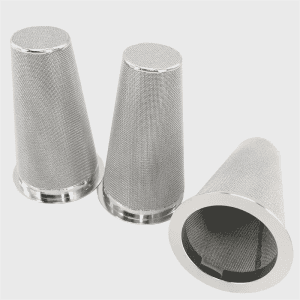
Choose a cone, flat-plate, or supported-mesh temporary strainer according to the available flange space, target debris size, flow direction, required open area, and service method. Cone geometry can provide more screening surface than a simple flat plate within a suitable pipe arrangement, but the actual usable area and pressure drop depend on the selected dimensions and perforation pattern.
| Screen configuration | Appropriate consideration | Main design check |
| Perforated cone | Initial interception of larger construction solids | Hole diameter, perforated open area, cone length, strength, and removal access |
| Cone with woven mesh and perforated backing | Smaller physical openings are required without leaving fine mesh unsupported | Actual mesh aperture, wire diameter, backing arrangement, and loaded differential pressure |
| Flat-plate temporary strainer | A short insertion geometry is needed at an approved flange location | Limited screening area, solids-holding capacity, and pressure-loss allowance |
| Sintered or multilayer cone | A particular project needs a different supported metal-media construction | Verified opening or retention basis, cleanability, compatibility, and hydraulic data |
Saifilter’s temporary cone strainers can be configured with perforated plate, precision woven wire mesh, or multilayer sintered mesh. The same product range includes flat-plate options. This matters during commissioning because the engineer can specify a structural support and screen opening for the actual debris duty instead of accepting one fixed screen design.
Cone length is an installation parameter, not just a catalogue dimension. For example, Saifilter’s reference table lists 8-, 10-, 12-, and 18-inch cone lengths among the options for a nominal 4-inch line. A longer element is only useful if the approved assembly provides the required internal space and its hydraulic and mechanical performance has been checked. The flange facing, pressure class, and final dimensions must be confirmed on the project drawing.
Screen orientation must follow the supplied drawing. Saifilter describes configurations in which woven metal mesh can be placed on the inner or outer side of a cone according to flow direction. The supporting perforated metal must resist the applied loading in that configuration. Do not install a mesh-backed cone by relying on a generic rule about which direction the tip or mesh should face.
How Do You Size a Temporary Strainer for Flushing?
Size the temporary strainer for the specified flushing flow, screen opening, effective open area, expected debris load, and maximum allowable pressure loss. Matching nominal pipe size alone does not show that the screen will pass the flow required to clean the selected loop.
What Flushing Flow Should the Screen Pass?
The screen must pass the design flushing flow for the pipe leg while remaining within the pump’s available capacity and the temporary assembly’s pressure limits. Calculate the required flow from the actual internal pipe area and the approved target mean velocity:
Flow rate = internal flow area × average velocity
Use consistent units and the actual pipe internal diameter. One published TCS pre-commissioning guideline gives the following U.S.-unit planning examples:
| Nominal pipe size | Reference velocity | Reference flushing flow |
| 3 in. | 3.84 ft/s | 105 gpm |
| 4 in. | 3.96 ft/s | 157 gpm |
| 6 in. | 4.13 ft/s | 416 gpm |
| 8 in. | 4.26 ft/s | 664 gpm |
These are reference flushing-flow values for the guideline’s pipework assumptions, not Saifilter strainer flow ratings or universal design requirements. The approved commissioning plan controls the actual target.
For example, a 4-inch line with an approved demand of approximately 157 gpm needs a screen assembly that can pass that flow both clean and at the permitted debris-loading limit. A reference 4-inch cone dimension does not demonstrate suitability. The screen’s available open area, support, material, allowable differential pressure, and upstream pumping conditions must also be reviewed.
What Screen Opening and Material Should Be Specified?
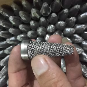
Specify the screen opening from the debris intended to be intercepted in that stage, then select the metal medium and backing that can withstand the expected flow and pressure loading. Perforated plate suits many coarse-debris duties; a woven layer provides a smaller physical aperture when the project requires finer screening, provided it has adequate support.
Saifilter offers a published 10–400 mesh selection range for temporary strainers, alongside carbon steel and stainless steel material options. These choices allow a screen to be specified for the identified service, but mesh count is not a micron efficiency rating. The clear aperture depends on wire diameter and weave; a nominally finer mesh can also load rapidly with startup debris. Request the actual aperture, construction drawing, and support details instead of selecting by mesh number alone.
Material selection must follow the cleaning fluid, operating temperature, corrosion requirements, and approved TCS wetted-material specification. The fact that carbon steel is a catalogue option does not make it acceptable for a TCS project requiring stainless steel wetted surfaces. Gasket and flange materials also need to be compatible with the temporary cleaning and flushing fluids.
How Do You Check Pressure Drop and Mechanical Strength?
Check the screen’s clean pressure drop, estimated loaded pressure drop, and differential-pressure strength against the available flushing-pump head and the allowable circuit resistance. The review should consider:
- Expected and maximum flow, fluid density, viscosity, and temperature.
- Screen opening, perforation pattern, exposed screening area, support thickness, and cone length.
- Debris quantity and how quickly the screen could become blinded.
- Maximum permissible pressure difference in the actual flow direction.
- Pump suction margin where relevant, plus hose, valve, and other temporary equipment losses.
- Access and isolation requirements for inspecting or changing a loaded screen.
Saifilter’s selectable screen constructions and cone dimensions make it possible to review these requirements against a proposed assembly. They do not establish a universal low-pressure-drop performance claim. If the selected configuration lacks a validated pressure-loss curve, request an application-specific engineering assessment before approving it for the flushing circuit.
How Do Temporary Strainers Work With Staged Filtration?
Temporary strainers usually serve as an initial coarse-screening stage, while finer filters and water-quality testing complete the pre-commissioning cleaning process. A temporary cone is useful for intercepting larger pieces of pipe scale, weld residue, and installation debris before they impose unnecessary loading on downstream fine-filter elements.
| Stage | Purpose | Where the temporary strainer fits | Evidence before moving forward |
| Initial debris removal | Intercept loose construction particles | Perforated or supported coarse screen, where specified in the flushing circuit | Debris inspection, flow continuity, and an acceptable pressure-loss trend |
| Progressive fine filtration | Reduce remaining suspended particles | Coarse screen may remain as upstream protection if the approved arrangement requires it | Fine-filter loading records and applicable particle or water-quality results |
| Final flushing and acceptance | Remove cleaning residues and confirm specified cleanliness | The temporary screen is not a substitute for final filtration or sampling | Project-defined conductivity, turbidity, chemistry, and other acceptance records |
For example, a published TCS procedure discusses starting filtration around 50–100 microns and progressing to finer media, with 5 microns given as a final filtration recommendation for that procedure. Those figures describe a staged flushing-filter arrangement. They do not mean that every temporary cone strainer is qualified for 5-micron service or that every facility-water loop requires that final grade.
The distinction has practical consequences. Saifilter’s perforated or supported-mesh temporary screens can be evaluated for the coarse stage when the debris and flow conditions justify them. A final cleanliness target may require separate fine filtration, chemical-residue flushing, and laboratory checks. Screen aperture alone cannot certify a cooling loop as clean enough for startup.
How Should Temporary Strainers Be Monitored During Flushing?
Monitor the temporary strainer by tracking flow, differential pressure, collected solids, and screen condition at the inspection frequency set by the approved flushing procedure. A rising pressure difference at comparable flow suggests increasing resistance, but it is not by itself proof of a blocked screen or a reason to exceed the pump’s operating limits.
Which Readings Should Be Recorded?
Record enough information to compare each cleaning pass with the previous one under similar operating conditions. The following field log covers the relevant variables:
| Field record | Why it matters |
| Date, pipe leg, strainer ID, and stage | Identifies where and when debris loading occurred |
| Flow rate, pump state, and valve positions | Confirms whether the planned path received the required flow |
| Upstream and downstream pressure | Determines pressure loss across the measured filter section |
| Fluid temperature and composition | Helps interpret changes in viscosity and pressure drop |
| Debris appearance, quantity, and screen condition | Shows contamination trends and detects damaged media |
| Cleaning or replacement action and post-service readings | Establishes whether the intervention restored the expected performance |
The measured differential pressure is upstream pressure minus downstream pressure, provided the taps span the intended strainer assembly. If they also span a hose, valve, or other equipment, the indicated loss includes those components. A comparison is meaningful only when the measurement points and operating conditions are known.
What Should You Do When Pressure Drop Rises?
When differential pressure reaches the approved service trigger, follow the flushing procedure to reduce or stop flow as required, isolate and depressurize the strainer section, and inspect the element. Do not simply raise pump speed to force water through an unexplained restriction.
A useful decision sequence is:
- Confirm the reading. Check flow, gauges or sensors, valve positions, and the actual pressure-tap locations.
- Compare similar conditions. Review the clean-screen baseline and the trend at comparable flow and temperature.
- Inspect the screen safely. After the required isolation and depressurization, document and remove collected debris using a compatible method.
- Decide whether to reuse it. Reinstall only if the mesh, perforated backing, seams, and sealing surfaces remain in the approved condition. Replace a damaged element rather than cleaning it again.
- Record the new baseline. Restart under the approved procedure and log the resulting flow and differential pressure.
Saifilter’s between-flange temporary screens can be removed for inspection, cleaning, or replacement after the line is made safe, allowing collected startup debris to be examined before the next pass. This is a useful maintenance feature during short-term, debris-heavy service, not a claim that the element can be opened under pressure or replaced without interrupting the isolated branch.
The distinction between a cleanable metal screen and one that needs replacement also applies later to permanent equipment during CDU strainer maintenance. The approved service thresholds and isolation arrangements, however, must be established separately for each installed assembly.
When Should Temporary Strainers Be Removed?
Remove the temporary strainer when its assigned debris-screening stage is complete, the project has accepted the required flushing and cleanliness evidence, and the approved final piping configuration calls for its removal. A screen that looks clean is not sufficient evidence that fine particles or cleaning residues have been cleared from the system.
Before removing or replacing the temporary installation, verify:
- Flow coverage: Every specified pipe leg, branch, and terminal connection has received the planned cleaning or flush, including locations where dead legs could retain debris.
- Operating records: Required flows were achieved, and filter pressure loss, solids collection, and screen-service events were documented.
- Water-quality results: The approved procedure’s particle, turbidity, conductivity, pH, and other relevant criteria have been met and recorded.
- Screen integrity: There is no evidence of torn screening media or detached fragments that might remain in the circuit.
- Mechanical handover: The temporary cone, plate, spacer, gasket, or spool has been removed or reconfigured as required by the final drawing and inspection procedure.
- Equipment readiness: The approved permanent filters and final equipment connections are in place before the circuit enters normal cooling service.
An approved startup element may remain for a defined later commissioning stage, but it should not become an undocumented permanent restriction. Permanent data center liquid cooling filters must be selected for their ongoing loop duty, flow, particle-retention requirement, coolant compatibility, and maintenance arrangement. They should not be specified merely by copying the temporary screen’s mesh grade.
What Specifications Are Needed for a Temporary Strainer?
A temporary strainer specification needs the piping dimensions, flow and pressure conditions, target screen opening, material requirements, installation orientation, and maintenance access. Supplying these details allows the proposed geometry and metal-media construction to be checked against the actual flushing duty.
| Required information | What to provide |
| System and flushing stage | Facility-water or TCS circuit, protected equipment, and whether the screen is for initial coarse interception |
| Approved location | P&ID, flange or spool drawing, flow direction, isolation arrangement, and accessible removal path |
| Pipe and connection | Nominal size, actual internal diameter if applicable, flange class, facing, dimensions, and standard |
| Screen geometry | Cone or flat-plate form, available axial clearance, required support, and insertion arrangement |
| Particle-retention requirement | Target debris size, perforation diameter or actual wire-mesh aperture, and supporting layer |
| Hydraulic requirement | Normal and maximum flushing flow, fluid properties, and permitted clean and loaded pressure loss |
| Mechanical requirement | Design pressure, temperature, maximum differential pressure in the relevant flow direction, and expected solids loading |
| Material and seal compatibility | Cleaning solution, procedure water, final coolant if relevant, metal grade, and gasket requirements |
| Maintenance and handover | Pressure-tap positions, inspection method, replacement screen availability, and removal plan |
Saifilter’s temporary strainer range provides a practical basis for this specification: cone and flat-plate forms, perforated and woven or sintered screen constructions, selectable metal grades, and reference dimensions covering different pipe and flange arrangements. These choices are useful only when the approved drawing confirms the screen will fit, withstand the actual loading direction, and pass the specified flushing flow.
A successful temporary strainer installation therefore has a defined screening task, verified hydraulic and mechanical conditions, monitored debris loading, and an agreed removal point. It contributes to commissioning by controlling the particles assigned to its stage, while the wider cleaning, fine-filtration, and acceptance program establishes readiness for liquid cooling operation.